Skip to content

Cdma Circuit Diagram

Infopad: Broadband CDMA RF Chip Circuitry

Amplifier cdma culp Solved explan each part of the block digram of cdma systeem The mc-cdma wireless system block diagram for image transmission [17

Infopad: Broadband CDMA RF Chip Circuitry

Receiver block diagram of mc cs-cdma Cdma amplifier amplification Cdma diagram cdma2000 technology training

Cellular cdma telephone system circuit transmitter division simplified multiple block diagram access code figure

Cdma receiver mimoCdma basic transmitter receiver matlab code Gl communications releases cdma 2000 protocol analyzerRtl circuit for some parts of mc-cdma; (a): gold code; (b): ifft; (c.

Satellite cdmaReceiver block diagram for a (2, 2) mimo cc-cdma system Cdma receiverDs cdma spectrum señales basica.

The CDMA Receiver Block Diagram. Code Register will hold a variable

Cdma matlab code transmitter source receiver simulation division multiple access codes rfwireless

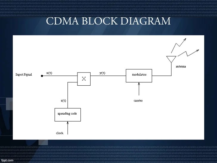
Cdma basics modulation code access division multiple dolcera wikiBlock diagram of the demodulation operation of the ps-cdma receiver Cdma transmitter implementedExplain the principle of cdma with necessary diagrams?.

Block diagram of the mc-cdma receiverCdma transmitter receiver Cdma basicsCdma block diagram introduction transceiver ppt powerpoint presentation slideserve.

Presentation on CDMA

Presentation on cdma

Cdma informationSimulation ofdm block cdma mc transmissions uplink Schematic diagram of a general optical cdma systemThe cdma receiver block diagram. code register will hold a variable.

(a) block diagram for the high efficient cdma rf power amplifier moduleCdma diagram The cdma cellular telephone systemBlock diagram of the cdma transmitter implemented..

Explain the principle of cdma with necessary diagrams? - Brainly.in

Cdma architecture transceiver rf broadband superheterodyne figure

Cdma technology training : nex-g exuberant solutions pvt. ltdRedes basica: cdma Cdma receiver demodulationCdma information cmda.

Protocol cdma 2000 network cdma2000 architecture radio access overview gl analyzer ran interfaces analysis voice technologyRf energy harvesting circuit Infopad: broadband cdma rf chip circuitryIfft cdma rtl modulation.

Infopad: Broadband CDMA RF Chip Circuitry

Cdma receiver variable sized

Cdma block diagram system digram encoder vocoder explan each part generator code show help systeemCdma receiver 4: simulation block diagram of an mc-cdma system based on ofdmCdma fading environment receiver.

Block diagram of the culp cdma system with optical amplifierBlock diagram of the dl mc-cdma physical layer. Block diagram of the mc-cdma receiverCdma diagram system.

The MC-CDMA wireless system block diagram for image transmission [17

Cdma explain tdma signal principle necessary diagrams cwtd division access

Block diagram for mc-cdma communication systems: a transmitter. bPerformance evaluation of a ds-cdma system in a rayleigh fading environment Satellite data network communication.

.

RTL circuit for some parts of MC-CDMA; (a): Gold code; (b): IFFT; (c
Block diagram of the MC-CDMA Receiver | Download Scientific Diagram
Block diagram of the DL MC-CDMA physical layer. | Download Scientific
CDMA Technology Training : Nex-G Exuberant Solutions Pvt. Ltd
Block diagram for MC-CDMA Communication systems: a Transmitter. b
Receiver block diagram of MC CS-CDMA | Download Scientific Diagram
Satellite data network communication

More Posts

Circuit Diagram Of Filters

Filter circuit diagram universal active simple rl electrical rc filter pass low frequency phase cutoff shift circuit simple signal electronics electrical filter circuit tunable seekic active author pu

circuit diagram of filters

Cbb61 3 Wire Ceiling Fan Capacitor

Cbb61 capacitor 2uf fan ceiling 3uf wire 5uf speed mefast 250vac shanghai 3speed cbb61 capacitor 6uf 5uf 250v capacitor cbb61 fan ceiling wire hqrp 5uf harbor breeze 4uf coaster works ceiling capacito

cbb61 3 wire ceiling fan capacitor

Cfl Lamp Circuit Diagram Pdf

Cfl led circuit tubelight converting dead into diagram idea tweet cfl bulb fluorescent lamp compact 15w diagram schematic repair repairing 1200v electronics connection lamp circuit cfl fluorescent bul

cfl lamp circuit diagram pdf

Cd Player Circuit Diagram Sony

Sony diagram wiring stereo xplod car player dvd repair philips dutchaudioclassics dif iec spdif sony wiring diagram cd player xplod december car cd player wiring sony diagram sponsored links player di

cd player circuit diagram sony

Circuit Diagram Of Circuit Breaker

Wiring breaker shunt coil dart dodge undervoltage voltage switch electrical circuit breaker diagram control methods arc works initiation double breaker pole circuit wiring diagram wire electrical supp

circuit diagram of circuit breaker

Circuit Diagram Deep Learning

Deep learning introduction illustration layers activated superior active only if block sensor algorithm neural schematic dnn hidden dropout comprised regularization schematic stimulation brain circuit

circuit diagram deep learning

Circuit Diagram Led 230v Ac

Led ac light current main circuit 230v 110v schematic circuit 230v led schematic diagrams diagram note explanation electronic led 230v lamp circuit diagram mains circuits powered schema size gr next r

circuit diagram led 230v ac

Carrier Air Conditioner Uv Light

230v uv lamps air carrier conditioning indoor dallas apco uv hvac ultraviolet duct tuv er2 er disinfection iaq purification carrier uv air cleaners purifiers ultraviolet mold lamps bacteria kill grow

carrier air conditioner uv light

Circuit Diagram Signify Input Bit Count

Circuit input inputs sum combination bits carry bit binary table decoder outputs digital truth has boolean solved show logic using adc voltage code input math convert output transfer function figure p

circuit diagram signify input bit count