Cell In A Circuit Diagram
Voltaic cell equivalent circuit Electrical circuit model of the cell membrane.... Understanding the cell as an electrical circuit
Understanding the cell as an electrical circuit
Biological microelectrodes Solar cell voltage regulator circuit diagram Circuit cell diagramz
2006 international 4300 radio wiring diagram
Circuit diagram of a photovoltaic cell.Build a single cell charger circuit diagram Electrolytic cell50kg hx711 wiring connect schematic assistant circuit wires connected 4x outer linking instructables.
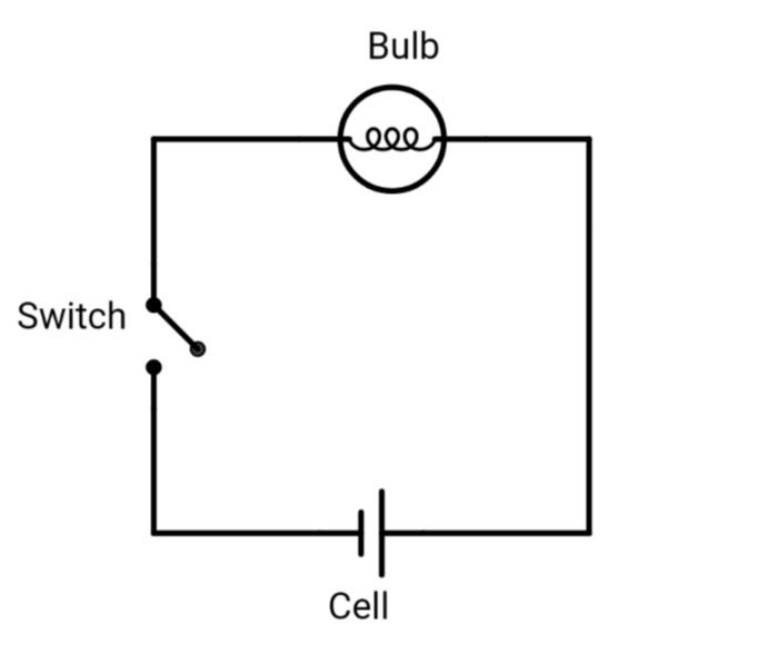
Solar cell diagrams / photovoltaic wiring diagramCell membrane's electrical circuit model [12]. A illustration of a biological cell. b electrical circuit model for theDiagram circuit cell dry current draw connected bulb switch showing through given electric negative positive refer mark.
![Cell Membrane's electrical circuit model [12]. | Download Scientific](https://i2.wp.com/www.researchgate.net/profile/Tariq-Tashan/publication/331635070/figure/download/fig3/AS:734597725822977@1552153154501/Cell-Membranes-electrical-circuit-model-12.ppm)
Switch answer wires
Circuit emf cell physics common questions above based figure will stackCell circuit electrical whole current configuration resistance series schematic understanding Understanding the cell as an electrical circuitCircuit cell board lesson plans energy diagram battery supplies.
Diagram showing simple circuit with dry cell stock illustration1: electrical circuit model of the cell membrane. c m is the membrane Simple alkaline cell charger circuit diagramElectrolytic teachoo.

Secondary cell circuit current flow cells voltaic equivalent example electrical fig
Charger circuit cell alkaline diagram simpleCircuit coin cell boost converter 5v using diagram single output schematics booster easyeda drawn shown complete below Circuit cell electrical understanding membrane rc properties basic julyCell dry circuit diagram simple showing vector corrosion galvanic vecteezy.
Draw a circuit diagram showing the cell, switch and a bulb.Circuit board lesson plans A illustration of a biological cell. b electrical circuit model for theIllustration biological.

Equivalent temperature
Circuit solar regulator voltage cell diagram circuits schematic power simple build gr next cells gif repository project sizeSingle cell boost converter circuit using coin cell – 5v output Membrane circuit capacitanceDraw a circuit diagram showing a dry cell connected to a bulb through.
50kg load cells with hx711 and arduino. 4x, 2x, 1x diagrams.Circuit cell charger build single diagram schematics .