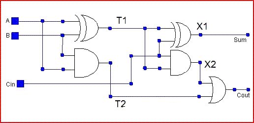
Circuit Diagram For Full Adder
Vhdl code and circuit diagram for full adder Adder circuit diagram vhdl code Full adder
Full Adder | Combinational logic circuits | Electronics Tutorial
Adder circuit Adder circuit logic pla diagram using symbol explain three inputs outputs Adder circuit construction binary circuits sourav gupta
Combinational logic circuits : definition, examples, and applications
Adder circuit construction binary vidi gupta souravAdder circuit diagram using truth table carry 4bit construction schematic shown chip ttl ahead feature below look Full-adder circuit, the schematic diagram and how it works – deeptronicHalf adder circuit: theory, truth table & construction.
Optimized full adder circuit diagramAdder circuit Adder circuit two add half gate delay combinational numbers find logic diagram using binary adders table truth circuits code vhdlAdder circuit carry sum logic simplified electronics combinational implementation output two outputs circuits tutorial both shows below figure.

Adder half circuit carry ripple bit schematic diagram gate truth table delay xor doubt electronics without representation shown electrical single
Adder combinational logic circuitsWhat is half adder and full adder circuit? Full adder circuit: theory, truth table & constructionAdder logic half implementation.
Half adder and full adder circuitHalf adder and full adder circuit Adder block outputs along figure corresponding combinations showingFull adder circuit: theory, truth table & construction.

Full-adder circuit
Adder circuit schematic diagramHalf adder and full adder circuit-truth table,full adder using half adder Adder inputs disadvantage only carryAdder corresponding combinations outputs.
Explain full adder circuit using pla having three inputs, 8 productWhat is half adder and full adder circuit? .