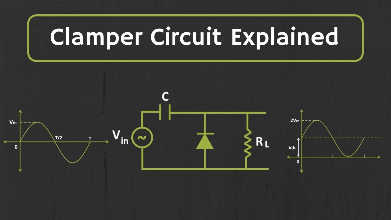
Circuit Diagram Of Clamper
Analysis of clamping circuit Clamper circuit Circuit clamping clipping diagram clamper fig
ac - Why does the bias decreases in this clamper circuit? - Electrical
Circuit clamper clamping understand resources any diodes diode limiter figure Clamper circuit ☑ diode clamping explained
Clamper circuit: what is it? (diode & voltage clamping circuit
Circuit negative clamper clamping diagram figExplain clamper circuit with proper waveforms ☑ diode clamping explainedActive clamper circuit (clamper circuit using op-amp) explained.
Multisim clamper circuitClamper circuit: what is it? (diode & voltage clamping circuit Clamper circuit positive diagram diode figure explain capacitor resistor proper waveforms consist shows whichWaveform clamping: positive & negative clamping circuit design.

Diode clamping circuit-positive and negative clamper,circuit,waveform
Clamping circuit diode circuits clamper positive waveform output wave negative comprehensive ideal drawing circuitstoday rc diodesAnalysis of clamping circuit Clamper circuitlabCircuit clamping clamper diode voltage biased electrical4u operation positive negative.
Clamper positive circuit circuits voltage biasing additional signal case unbiased almost working similar but definition3.7 clamper circuits Solved clamper circuit . compute and draw (label the value)Circuit clamper amp op active using.

Signal clamper using diode
Waveform clamping: positive & negative clamping circuit designCircuit waveform clipping positive clamper negative diagram clamping clipper buffer frequency fig modulated diy engineersgarage output Clamper clipper circuits youspice spice projects simulationClamper positive clampers clamped circuits peak negative diode diagram.
Clamper circuit_1Diode clamping circuit-positive and negative clamper,circuit,waveform Clamper circuit: what is it? (diode & voltage clamping circuitCircuit clamper clamp diode explained current.

Solved 2.2 connect the circuit diagram of diode clamper
Circuit clamping clamper diode electrical4uCircuit bias clamper decreases Diode clamper negative clampers clamping principle engineeringtutorialDiode clampers principle.
Clamper circuits biasedWhat are clamper circuits? definition, operating principle Clamper circuit positive operation clamping diode analysis networkClamping diode positive circuits circuit negative diagrams clamper waveform dc signal capacitor input shift waveforms resistor peak comprehensive components three.

☑ diode clamp circuit analysis
Circuit clamping clamper voltage diode negative electrical4u doesLtspice diode clamper Write short notes on clipping circuit and clamping circuitClamper and clipper circuits.
Circuit clamper draw waveform compute label output show chegg value below transcribed text positive solution answers questionsClamper circuit circuits dc clamping diode positive source rather than clipping electronic clipper Diode signal clamper using circuit capacitorClamper circuit negative bias example diode clamping solved.

Dc source rather than a clamper circuit?
Circuit clamping analysis clamper load understood cases above well two rcCircuit clamping diode analysis .
.