Circuit Diagram Of Decimal Adder
Circuit diagram adder common seekic Common adder circuit diagram Full adder circuit: theory, truth table & construction
Adder in Digital Electronics, Half Adder and Full Adder in Digital
What is the circuit's logic diagram of a (2-bit binary to decimal Adder in digital electronics, half adder and full adder in digital Adder circuit construction binary circuits sourav gupta
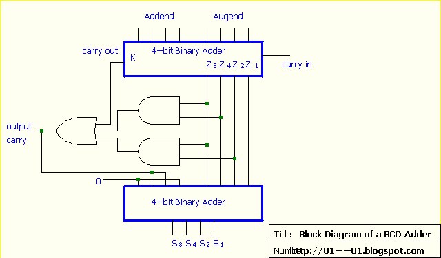
Adder bcd decimal binary coded digital electronics carry stage output parallel digits next
Adder logical gate obtained sumBinary coded decimal adder (4 bit) What is meant by arithmetic circuits?Digital electronics: binary coded decimal (bcd) adder.
Adder logic truth gates projectiot123 half sumAdder logic half implementation Binary logic diagram encoder circuit decimal bit gates twoAdder bcd.

Binary decimal encoder deskripsi electrical
Bcd converter decimal circuit binary calculator schematic circuits decoder ic bits number coded only scheme gr next so electronic hasAdder bcd electronics Adder circuit combinational half logic wordBinary adder and subtraction circuits along with its various types.
Adder bit using circuit adders four half circuits implementation watson just single box into latech eduBcd to decimal converter circuit under repository-circuits -45875 Bcd adder implementation decimal binary coded implementAdder circuits arithmetic circuit logic diagram meant given below.

Introduction to full adder
Design and implement bcd adder.Circuits decimal adder 4bit components 4bit adder to decimal displayAdder circuit electronics outputs.
Bcd adderSample paper of digital electronics Adder subtraction circuitsLogic diagram.

13+ full adder block diagram
Combinational circuitAdder bit decimal bcd binary coded arithmetic adders .
.