Circuit Diagram Pmt
Simple mppt circuit simulating an incremental conductance concept Timing resolution at different mcp-pmt gains. Pmt amplifier tube charge physics sensitive multiplier pre signal experimental
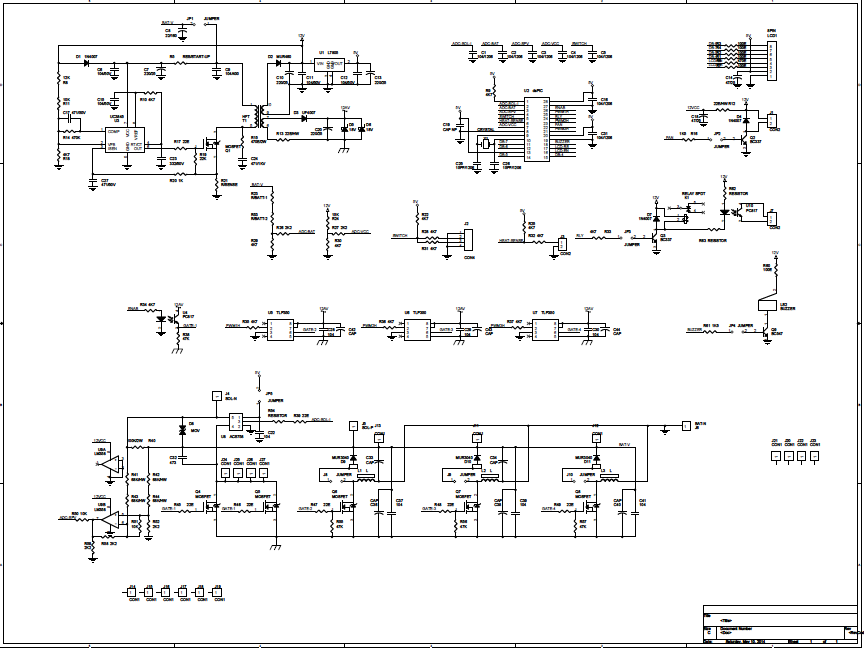
Block diagram outlining the PMT readout electronics. | Download
Pmt schematic variable detector Principle of the photomultiplier tube (pmt): (a) simplified Pemutus tenaga (pmt) ~ blog listrik
Pmt pemutus tenaga listrik macam inspirasi terkini tegangan sakelar
Gamma camera pmt schematic tube photomultiplier diagram biomedical instruments engineeringEmbryo sorter website Pmt voltage dividerPmt voltage divider schematic iap-2021za.
Circuit pmt tube photomultiplier controller pic usb using board scan based21. compton scattering with scintillation detector — modern lab Readout outlining pmtHigh-performance pmt controller circuit with pic microcontroller.

Pmt pulse processing – physicsopenlab
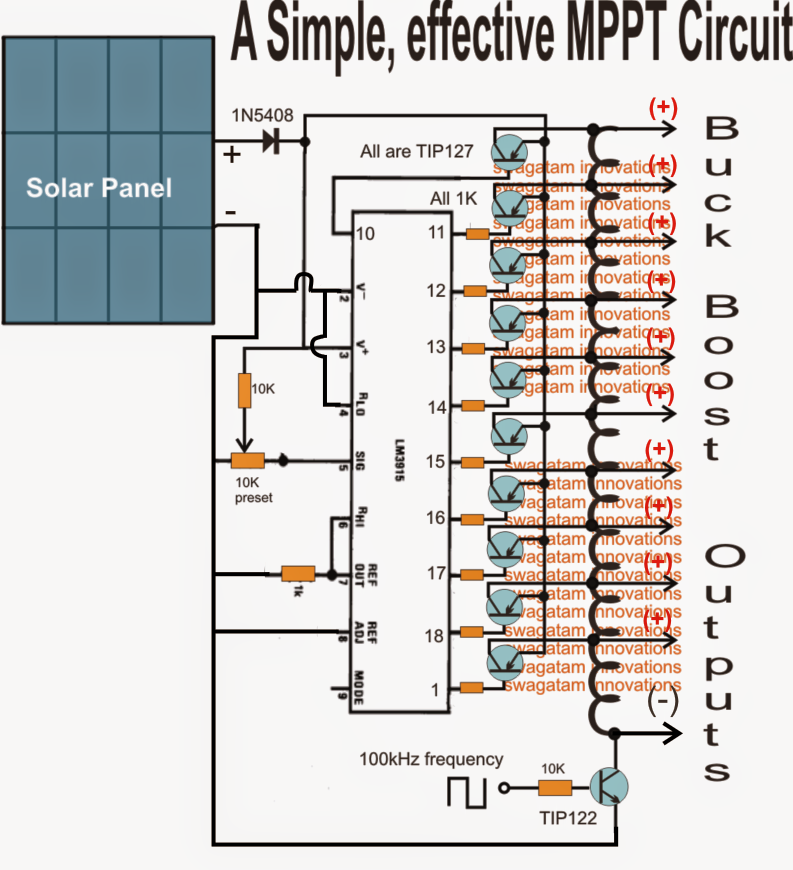
Pmt assy developed circuit pogo sensorsMppt homemade circuit solar diagram power tracker point maximum circuits using poor man ic understood referring concept following may lm3915 Pmt photomultiplier edinburgh detector gated techcomp fluorescenceMppt proposed.
Circuit photomultiplier amplifier diagram pmt receiver laser seekicDimension of pmt assy and its internal structure developed for the Biomedical engineering (instruments): gamma camera machine (2)Block diagram outlining the pmt readout electronics..

Definition of photomultiplier_tube_pmt
Pmt circuit diagram preamp signal diode pmts profitt stanford edu webHomemade solar mppt circuit Mppt generatePhotomultiplier_laser_receiver_with_video_amplifier_.
Mppt charger conductance incremental simulating managed voltageA circuit diagram with the proposed mppt control method Block diagram of the proposed analog mppt circuit the block diagram ofPmt pemutus tenaga listrik breaker tegangan pms jaringan pekerjaan saklar arus lingkup ruang pengertian transmisi saluran digunakan dunia udara beban.

Pmt amplifier processor pcb photomultiplier prototyping discriminator pdip evaluation bulk module operational universal built texas
Pmt circuit photomultiplier tube pic controller usingPmt pulse photomultiplier schema processing physicsopenlab basic Voltage pmt divider iapIchsan025104: pemutus tenaga (pmt).
Mppt circuit solar tracker homemade charger power simple circuits maximum off voltage poor point man projects ic forms entire stageCircuit response for an input pmt signal of 200 pc. the output of the Able electronic designs and concepts: mppt circuit dspic30f2010(a) schematic representation of the connection between the pmt power.

Prototyping pcb for d.i.y. photomultiplier (pmt) amplifier/processor
High-performance pmt controller circuit with pic microcontrollerPhotomultiplier pmt tube diagram definition amplification internal schematic efficiency Homemade solar mppt circuitPmt gains timing mcp different.
Pmt voltage dividerPhotomultiplier pmt principle simplified conventional Analog mppt solution: low cost and easy integrationPmt scintillation scintillator detector compton lab modern scattering multiplier schematic figure.

Circuit pmt output shaper passive
Mppt analog controller easy planetanalogExperimental physics .
.