Circuit Diagram Power Loop Test Loop
Troubleshooting loops wiring Physics rules figure circuit kirchhoff current voltage diagram complex sources two through loops three kirchhoffs points chapter sub branch Instrumentation loop test loop checking paktechpoint
21.3 Kirchhoff’s Rules – College Physics: OpenStax
Power loop field tools source Using loop power for process instrument and 4-20 ma loop testing Troubleshooting current loops
Understanding current loop output sensors
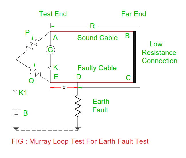
Murray loopEarth loop impedance testing demystified Loop test murray principle fault topics electrical balance usedTransmitter wire loop powered diagram current control electronic analog loops output circuitry circle previous.
Electrical topics: working principle of murray loop testUnderstanding current loop output sensors Murray fault electricalField tools loop power – microflex.
Instrument calibration fluke
Loop current 20ma circuit tester schematic power below pdf version drawing clickLoop current output sensors power understanding typical ma figure What is an instrumentation loop diagram?Loop diagram instrumentation control field instrument plc scada industrial room organize sections divided information into.
Loop power powered devices instrumentation indicator basics animation gif characteristics instrumentationtoolsUsing loop power for process instrument and 4-20 ma loop testing Instrumentation checking paktechpointElectrical revolution: murray loop test.

Loop power process ma using 20 instrument testing fluke calibration 2021 may
Basics of loop powered devicesThe science of 4 to 20 ma current loops 21.3 kirchhoff’s rules – college physics: openstaxMeter loop wiring diagram.
Circuit loops loop path closed any laws lecture basic ppt powerpoint presentationMurray loop test || power system analysis Loop indicatorLoop testing impedance tester megger earth test fault diagram electrical demystified.

2-wire (“loop-powered”) transmitter current loops
Circuit: 4 – 20ma current loop tester__ circuit designed by david aLoops bapihvac .
.


