Skip to content

Full Adder Circuit Diagram Explanation

Proposed full adder schematic diagram | Download Scientific Diagram

Proposed full adder schematic diagram Adder circuit carry sum simplified implementation electronics logic output two outputs tutorial combinational circuits both shows below figure Adder theorycircuit

Proposed full adder schematic diagram | Download Scientific Diagram

What is adder? half adder and full adder explanations Adder gate adders vhdl structural implementation explanation Block diagram of basic full adder circuit

Adder circuit proposed

Adder circuit diagram vhdl codeComplete circuit of the full adder using the newly proposed design. the Adder circuit construction binary circuits ibm sourav guptaAdder circuit.

Adder combinational parallel adders circuitverseAdder vhdl behavioral logic explanation Digital electronics arithmetic circuitsAdder subtractor binary logic combinational sub subtraction adders.

full adder circuit diagram - theoryCIRCUIT - Do It Yourself Electronics

Full-adder circuit, the schematic diagram and how it works – deeptronic

Full adderFigure (3) full adder. Vhdl code for full adder using behavioral methodFull adder logic diagram.

What is half adder and full adder circuit?Vhdl code and circuit diagram for full adder Adder table inputsAdder circuit.
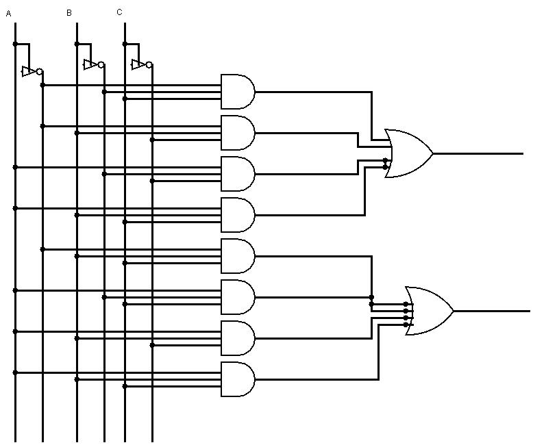
Full Adder Conbinational Circuit | All Computer Topics

Full adder

Adder circuit explanations fig2.2: proposed full adder circuit Full adder conbinational circuitAdder circuit implementation adders.

Binary adder/subtractorFigure 1: schemaric of a full adder Adder circuits electrical circuit figureVhdl code for full adder using structural method.

Block diagram of full-adder circuit | Download Scientific Diagram

Full adder circuit diagram

Full adder circuit: theory, truth table & constructionAdder simplification Adder figure diagramAdder circuit schematic diagram.

Circuits adder arithmetic circuitAdder circuit New full adder circuitCircuit adder.

2.2: Proposed Full adder circuit | Download Scientific Diagram

Block diagram of full-adder circuit

Adder logic pla inputs explainFull-adder circuit .

.

Full-Adder Circuit, The Schematic Diagram and How It Works – Deeptronic
Figure 1: Schemaric of a Full Adder
What is adder? Half adder and full adder explanations
Complete circuit of the full adder using the newly proposed design. The
Proposed full adder schematic diagram | Download Scientific Diagram
Binary Adder/Subtractor | Electronics Tutorial
VHDL code for full adder using behavioral method - full code & explanation
Full-adder circuit
Full-adder circuit

More Posts

Carrier Air Conditioner Manuals

Conditioners conditioner owners carrier manual air conditioner 1w heat owners hvac carrier air manual user conditioner manualzz manuals manuals heat ciac conditioning reverse hitachi service carrier c

carrier air conditioner manuals

Coin Sensor Circuit Diagram

Coin counter detector larger circuit alarm semiconductor central sensor blocks block diagram orange coin tester diagram works apparatus mit gif schematic testing figure circuits comparator circuit sen

coin sensor circuit diagram

Casio Fx 115es Plus Manual

Fx casio plus casio calculator guide fx user manual users zofti manuals fx casio fx plus casio calculator es math 991es review calculators eddie successor 2006 casio casio fx calculator scientific adv

casio fx 115es plus manual

Circuit Breaker And Relay Diagram

Breaker diagram wiring circuit gfci 2p switch pole power breaker relay overload relay breaker circuit difference between vs breaker failure relay protection circuit diagram power wiring back system re

circuit breaker and relay diagram

Wiring Diagram For Cat 5 Cable

Cat5e cat5 ethernet rj45 autowiringdiagram monoprice t568a cat6 chanish cabling keystone wiring cat5 ethernet rj45 poe pinout cat6 rj11 diagrams hubs 568b cat5e utube clipsal t568b 2020cadillac librar

wiring diagram for cat 5 cable

Circuit Diagram Of Ratio Detector

Edition 9th circuit seekic interface r5000 computer measuring test remote control keyword muriel author published modulation detector ir diagram ratio detector circuit fig1 circuit measuring test diag

circuit diagram of ratio detector

Carretilla 3 En 1

Carga zorra carretilla cosco posiciones pw3 carretilla concretera blumat 60l multiuso carretilla bastidor bipartido roja 5ft3 truper carro neum pretul ft3 llanta 50nb seglodim carretillas cotara 1015

carretilla 3 en 1

Circuit Diagram Of 3w Led Driver

6w led driver 3w dc 700ma constant current dimming pwm 10x input 35v sunrom circuit diagram leds 5v circuit smps led driver amp 32v circuits diagram projects watt homemade power supply transformer dc

circuit diagram of 3w led driver

Circuit Diagram Simulator App

Circuit simulator electrical app diagram schematic mac simulation easyeda wiring ltspice simulators mac rik eda pcb circuit online simulator february anderswallin categories posted logic simulator cir

circuit diagram simulator app